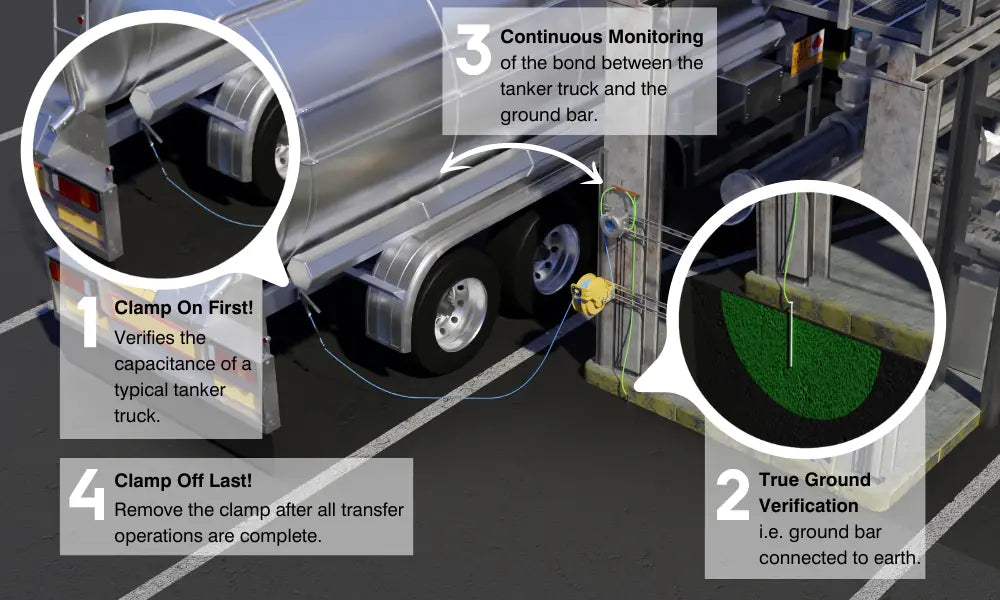

Highlights
- Description
- Technical Data
Description
GET A QUOTE – For business orders requiring a written quote or for volume pricing please request a quote.
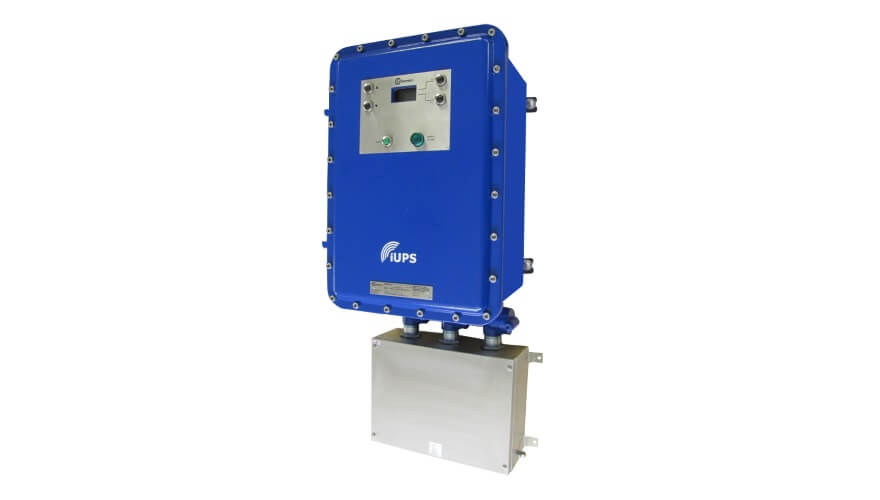
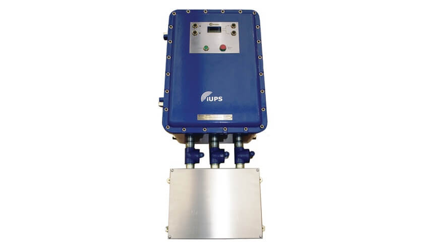
Our CID2 AC-UPS systems deliver clean, uninterrupted power within hazardous areas using an online double-conversion design with pure sine-wave output (<3% THD). Its seamless 0 ms transfer ensures critical systems like controls, computing, and instrumentation remain operational during outages or voltage disturbances.
With over 94% efficiency in AC mode and above 90% on battery, the UPS minimizes energy loss and heat, reducing cooling needs and long-term operating costs.
It offers scalable and redundant configurations, allowing parallel operation for higher capacity or failover protection.
Advanced monitoring and integration through USB and RS interfaces enable real-time diagnostics with SCADA or PLC systems. The system’s IQ-Technology predicts battery health and provides early warnings, supporting proactive maintenance.
Built for industrial reliability, the unit operates from –25 °C to +60 °C, meets EMC and vibration standards, and tolerates overloads for short periods—ideal for harsh or high-demand environments
| System Part Number | System Input & Output Voltage (VAC) | System kVA | Battery Bank Size (kWh) |
|---|---|---|---|
| CID2-AC-UPS-120-2.5 | 120 | 2.5 | 5.28 |
| CID2-AC-UPS-120-5.0 | 120 | 5 | 10.56 |
| CID2-AC-UPS-230-2.5 | 230 | 2.5 | 5.76 |
| CID2-AC-UPS-230-5.0 | 230 | 5 | 10.56 |
| CID2-AC-UPS-230-7.5 | 230 | 7.5 | 10.56 |
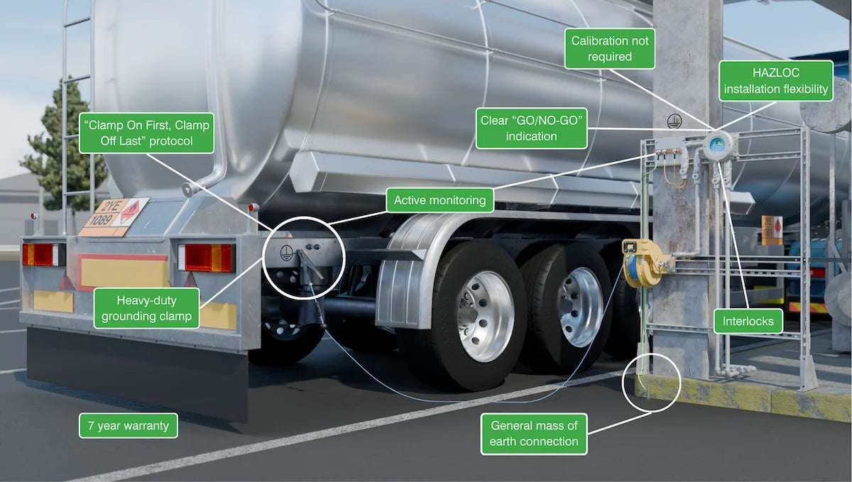
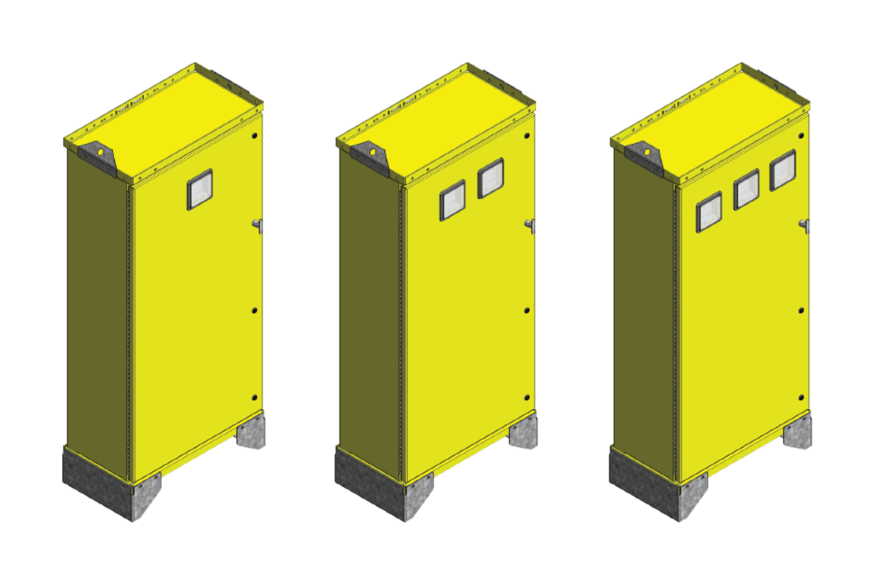
NOTE: All systems include input surge protector, input CB, output CBs. The pictured enclosures are shown with a powder-coated Safety Yellow finish, which can be changed per customer request.

Technical Data
| Input Data | |
| Input Voltage |
100V AC -10% / +20% 110V AC -10% / +20% 120V AC -10% / +15% 130V AC -15% / +10% |
| Frequency Range (fin) | 47.5 Hz … 52.5 Hz |
| Bypass Fuse | 40 A T 250 V |
| Current Consumption | nom. 24 A (120V AC) |
| Rated Short-Time Current Carrying Capacity Icw | 6 kA |
| Mains Operation | |
| Output Voltage |
100V AC ±2% 110V AC ±2% 120V AC ±2% 130V AC ±2% |
| Form of Output Voltage | Pure sine |
| Output Current | nom. 20.8 A (120V AC) |
| Maximum No-Load Power Dissipation | 9 W |
| Power Loss Nominal Load Max. | < 120 W (100% load, battery charged) |
| Nominal Output Frequency | 50 Hz / 60 Hz |
| Output Data | |
| Efficiency | > 94% (100% load, battery charged) |
| Apparent Power | 2500 VA |
| Real Power | 2250 W |
| Power Factor (cos φ) | 0.9 |
| Crest Factor | 2.5 |
| Switch-Over Time | 0 ms |
| Overload Capacity Mains Operation | 120% … 150% (20 s / 5 s, then switch to bypass operation) |
| Overload Capacity Battery Operation | 120% … 150% (20 s / 5 s, then shutdown) |
| Overload Capacity Bypass Mode | 120% … 150% for a sustained period / 20 s, then shutdown |
| Rated Short-Time Current Carrying Capacity Icw | 6 kA |
| Energy Storage Output | |
| Short-Circuit Current | 650 A (<1.5 ms) |
| Energy Storage General | |
| Permissible Backup Fuse | 40 A |
| Temperature Sensor | Yes |
| Signal Output Alarm | |
| Switching Output | Transistor output, active |
| Output Voltage | 24 V |
| Continuous Load Current | ≤20 mA |
| Signal Output Battery Mode | |
| Switching Output | Transistor output, active |
| Output Voltage | 24 V |
| Continuous Load Current | ≤20 mA |
| Signal Output Power Good | |
| Switching Output | Transistor output, active |
| Output Voltage | 24 V |
| Continuous Load Current | ≤20 mA |
| Signal Output Ready | |
| Switching Output | Transistor output, active |
| Continuous Load Current | ≤20 mA |
| Signal Output P > Pn | |
| Switching Output | Transistor output, active |
| Output Voltage | 24 V |
| Continuous Load Current | ≤20 mA |
| Signal Output Service Required | |
| Switching Output | Transistor output, active |
| Output Voltage | 24 V |
| Continuous Load Current | ≤20 mA |
| Signal Ground SGnd | |
| Function | Signal ground |
| Reference Potential | For signal inputs & signal outputs |
| Ambient Conditions | |
| Ambient Temperature (Operation) | -25°C … 60°C (>50°C: 2.5%/K) |
Related Product